I’ve been researching a few ideas for antenna’s over the last month which inspired me to create the biggest antenna I think I’ve ever built – the mighty v-beam!!
But let’s rewind a few steps – what I am really interested in is broadband antennas. There are many designs for broadband antennas but one thing many have in common is a terminating resistor and a corresponding impedance matching balun. Common values of these tend to be a 500 ohm load with a 9:1 balun or a 800 ohm load with a 16:1 balun so it makes sense to start with these components:
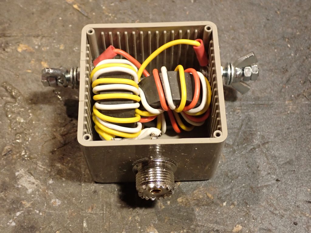
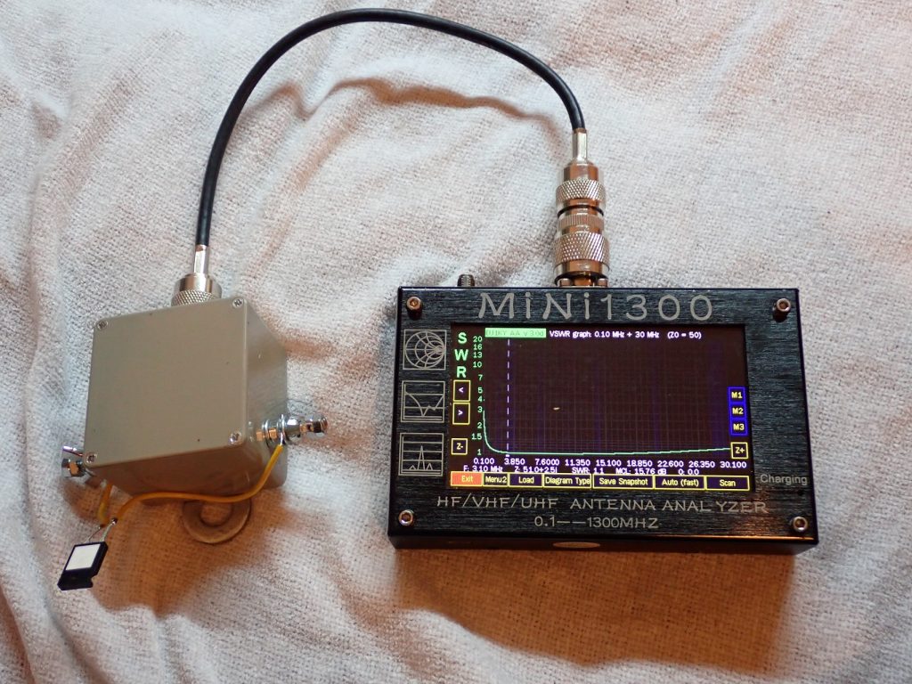
Using these excellent guides from VK6YSF and HF Kits I created a 9:1 balun for impedance matching and a 1:1 choke unun/balun. These are both mounted into a single enclosure to provide both impedance matching and reduce common-mode currents flowing in the coax outer. Note the two toroids are mounted at 90 degrees to reduce any interaction in their magnetic fields. The SWR is low across the HF range which is promising.
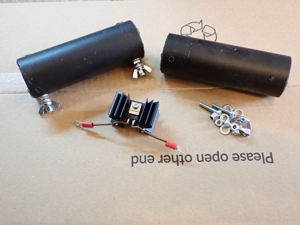
For my 500 ohm load resistors I found some cost effective non-inductive resistors from RS (part number 862-5739) for around £8 each. When fitted to a heatsink these can handle up to 50w of power so should be more than sufficient for my 100w transceiver. As a rule of thumb terminating resistors should be specified at around 30% of transmitter power and I mostly operate using SSB so the average power is actually considerably less than the radios 100w specification. I fitted these inside some old plastic tubing with some M4 machine screws for connecting antenna wire.
Using these parts I can now create a number of broadband antenna’s
- Terminated folded dipole
- Terminated dipole
- V-Beam
- Beverage
So there will be plenty to experiment with. But for now I’m interested in the v-beam. Why? Because this offers up to 11dBi of gain which rivals a yagi antenna. The trade-off is it’s big, really big! To get the maximum gain the antenna needs to be greater than 5 wavelengths long:
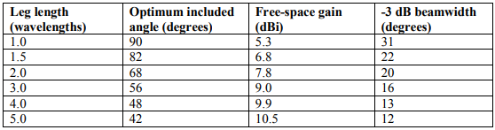
A standard military design seems to be to make a giant triangle where the wire elements are 80m long with around 50m between the ends which gives a 35 degree angle at the apex. This will be over 5 wavelengths anywhere above the 15m band and more than one for the whole HF band. The included angle is a bit small but research online indicates this might not be so critical.
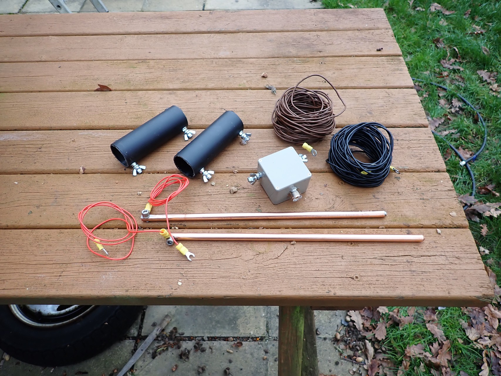
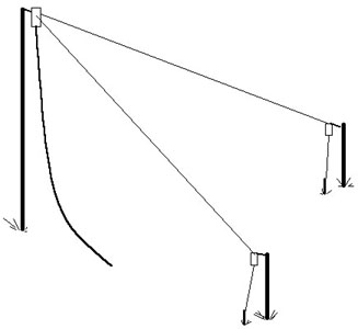
At the end of each leg there is a resistor and an earth spike which dissipate any residual power where the antenna is non-resonant. The full kit looks like this:

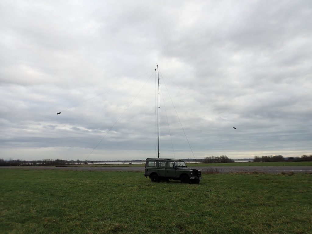
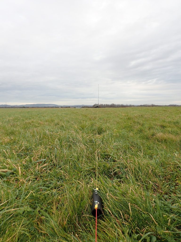
For initial testing I ran the antenna in my garden but I had to make it much smaller than ideal due to space constraints, the initial object was just to confirm it worked and presented a good VSWR match. For the real test I invested in a 500m spool of wire and headed for a local POTA location with plenty of space.
For the testing I initially set up some dipoles for 10, 20 and 40m and ran some WSPR cycles on them. Then I built the mighty v and repeated the WSPR cycles before switching to voice for some POTA on 10 and 15m.
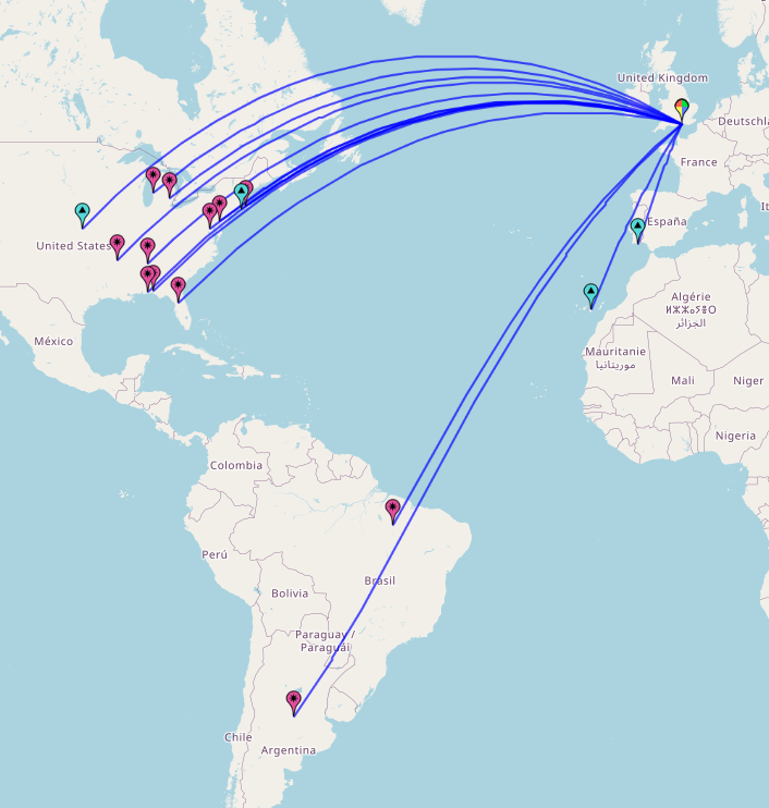
The results – well mixed. Using WSPR I was expecting to see a clear improvement in SNR between the dipole and v-beam in the direction I was transmitting (towards North America) however looking at the data I could see reporters showing better SNR on the v-beam, others reporting the opposite and some showing no change! What is clear though is the antenna is significantly more directional with far fewer reporters in Europe when the v-beam was in use.


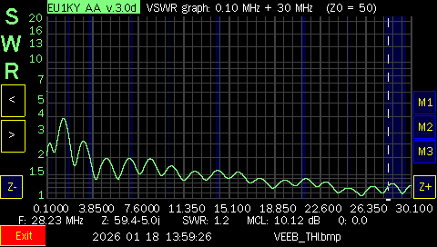
The VSWR plot looks great across the HF band with no need for the ATU in the radio.
On voice I was able to make plenty of QSOs in North and South America although I did not have time to also try voice with the dipole so who knows if this was an improvement! Note all the QSOs are in the direction the antenna is designed to operate it. I didn’t make any QSOs in Central Europe despite the band being open and plenty of stations on the air.
What next – I might try testing with a smaller version of the antenna – perhaps 50m in length with a 45 degree angle which might be a good compromise for a little less gain but also a little less space. Also I would like to test some other antenna’s that can be constructed with the same constituent parts – the Beverage might be an interesting experiment….